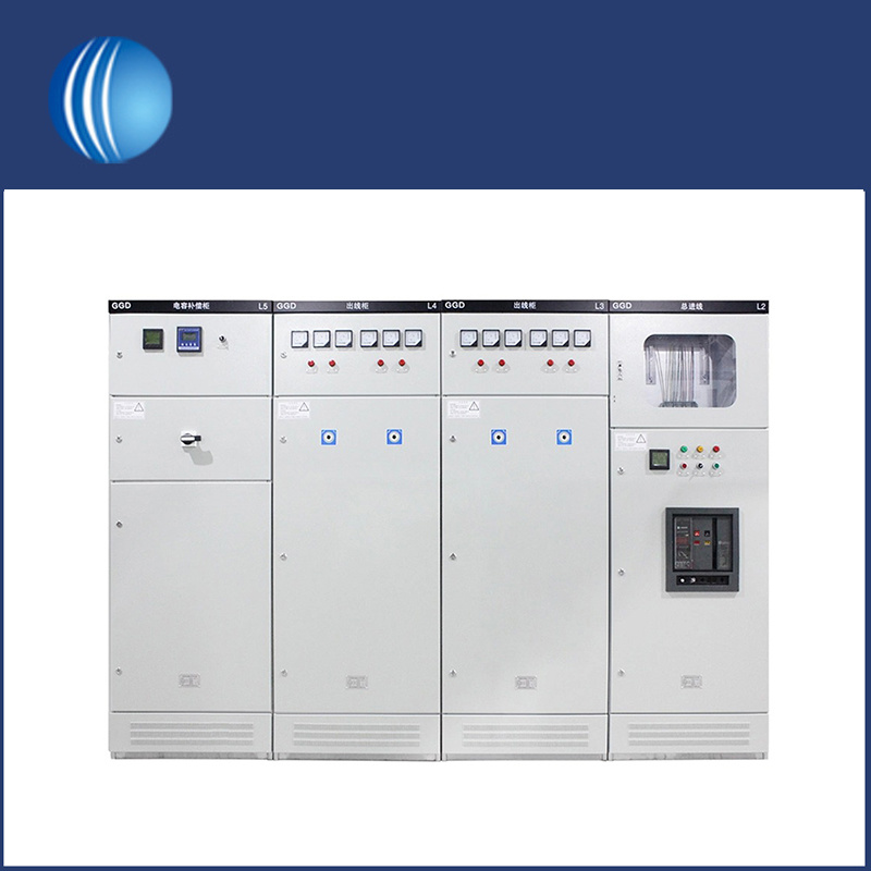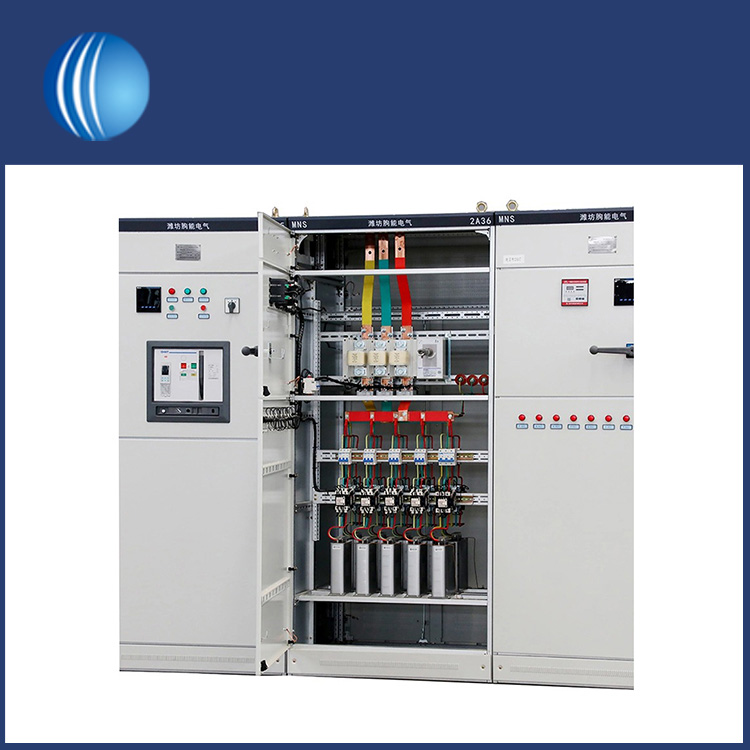
Gas insulated switchgear (GIS) has become an important part of the grid infrastructure. GIS is an electrical component that uses a gas such as sulphur hexafluoride (SF6) as a dielectric to isolate electrical conductors.Specialist manufacturer for the Shouke® electrical industry.
Gas insulated switchgear (GIS) is an essential component of power grid infrastructure and offers multiple advantages over conventional air-insulated switchgear, including smaller size, lighter weight, higher reliability, improved safety, lower maintenance and operating costs, and better environmental performance. By using GIS, power grid infrastructure can operate more efficiently and effectively.
Reduced size and weight
Gas insulated switchgear reduces size and weight compared to conventional air-insulated switchgear. The use of SF6 gas allows for a compact and lightweight GIS design, making it easier to install and operate in confined spaces, such as substations in urban areas.
Increased Reliability
Gas insulated switchgear is highly reliable and, unlike air-insulated switchgear, GIS is well suited to harsh environments where dust, humidity and salt contamination can affect the operation of electrical components. In addition, GIS is less affected by temperature changes, which can affect the operation of conventional air-insulated switchgear.
Improved safety
Gas insulated switchgear offers a high degree of safety, using SF6 gas as the dielectric medium, which is non-toxic, non-flammable and has excellent electrical properties. It is therefore an ideal electrical insulation medium. In addition, the use of SF6 gas in GIS circuit breakers significantly reduces the risk of explosion or fire compared to air-insulated switchgear.
Reduced maintenance and operating costs
Compared to conventional air-insulated switchgear, gas insulated switchgear significantly reduces maintenance requirements and operating costs over its lifetime. SF6 gas has a longer service life than air, reducing the need for frequent maintenance and replacement of electrical components. In addition, due to its high efficiency, reliability and low maintenance requirements, GIS has lower operating costs.
Improved environmental performance
Gas insulated switchgear is environmentally friendly compared to conventional air-insulated switchgear. SF6 gas is chemically stable and does not react with other substances or elements, making it an ideal environmentally friendly electrical insulator. In addition, SF6 gas has no effect on the ozone layer and does not contribute to global warming.

How to disassemble and assemble?
For maintenance and repair of gas insulated switchgear, engineers may need to disassemble and assemble the equipment.
Step 1: Preparation
Before disassembling gas-insulated switchgear, engineers should prepare some tools and documents:
- Safety glasses, gloves and shoes to protect themselves from potential hazards.
- A digital camera or hand-drawn sketchbook to record the assembly process.
- Relevant documents such as maintenance manuals and circuit diagrams.
Step 2: Decompression
Gas insulated switchgear is designed to operate at high voltages. Therefore, before disassembling the GIS, the engineer should first depressurise the equipment to a safe level. The following steps are recommended:
- Open the valve between the GIS and the gas handling equipment.
- Suction the gas out of the GIS until the pressure reaches atmospheric levels.
- Verify the pressure with a pressure gauge.
Step 3: Disconnection
The next step is to disconnect the gas insulated switchgear from the power supply and accessories. It is recommended that the engineer follow the reverse order of installation:
- Disconnect the cable connector between the GIS and the transformer or generator.
- Disconnect the gas insulated busbar (GIB) between the two GIS sections.
- Disconnect the earth cable.
- Disconnect the ground cable. Remove the SF6 gas line and valve assembly from the GIS.
Step 4: Disassembly
After disconnecting the gas insulated switchgear, the engineer can disassemble the equipment section by section. It is important to follow the dismantling sequence specified in the maintenance manual. The following are some typical steps:
- Remove the covers and protectors of the GIS using appropriate tools.
- Unscrew the bolts and nuts securing one section of the GIS to another.
- Remove the section carefully without damaging the components or insulators.
Step 5: Replacement and Assembly
If any gas insulated switchgear component is damaged or has reached the end of its useful life, the engineer should replace it with a new one. It is important to use the original manufacturer's components and follow the torque specifications for the bolts and nuts. Below are some typical assembly steps:
- Install the new assembly in the correct orientation and position.
- Tighten the bolts and nuts to the defined pattern and torque to avoid distortion.
- Install the cover and protector in the reverse order of disassembly.
Step 6: Inspection and Testing
After assembly, the engineer should carry out inspections and tests to ensure the reliability and safety of the gas insulated switchgear. The following checks are recommended:
- Check that all cables and connections have been correctly reconnected.
- Verify the pressure and purity of the gas in the GIS and refill if necessary.
- Carry out electrical tests, e.g. insulation resistance test and partial discharge test.
Disassembling and assembling gas insulated switchgear is a complex and critical task. It is vital that maintenance manuals are followed closely and that the necessary tools and documentation are available. In addition, engineers should always wear protective equipment and be aware of potential hazards. By following these steps, engineers can maintain and repair GIS efficiently and effectively, ensuring safe and reliable operation.
Please do not hesitate to contact us if you have any requirements.
